GBA Afterburner Backlight

Game Boy Advance Afterburner Backlight Installation Tips


Who needs to upgrade from a GBA to a GBA SP when you can get an Afterburner kit?

I tried out the GBA SP in a local Electronics Boutique and was quite excited by the:
However, I was dissappointed by the:
All I really wanted out of a GBA SP was the backlit display. I have not only NiMH AA cells, but also a Nyko Shock 'N' Rock with NiMH batteries, big speakers, and a rumble feature built-in. The buttons of my GBA, while a little small on my fingertips (compared to the original Game Boy), are easily accessible by my not-so-childlike hands, and playing it is especially comfortable with the Shock 'N' Rock attached. I couldn't forsee trading in my beloved transparent Glacier GBA (a gift from my brother) and $60 for a GBA SP...


So I mail-ordered an Afterburner kit from Lik-Sang.

Specifically, I ordered the GBA Afterburner Pack SP^2 (Milky Blue) kit. True to their words, the package arrived in less than the 2 weeks following the order, and it did contain all the parts necessary to perform a professional, custom installation. I'm proud to say, that with my fiancee's help, within 3 hours, I had a nicely backlit GBA (with the cool "fringe" glow courtesy of the transparent case) controlled via the dimmer chip (front panel button control instead of a dial).

There were three significant advantages going with Lik-Sang's kit: After reading all of the online horror stories about this process, especially the anti-reflective film lamination being so incredibly difficult, I ordered an extra anti-reflective film with my order, just so that I would have a backup should we fail the first time.


Prior to assembly...

I reviewed the included instructions carefully and identified the parts included in the little bags. The included instruction booklet (direct from Triton Labs) discussed only how to wire up the Afterburner kit with either no dimmer control or a "dial" or potentiometer-controlled dimmer, not the dimmer chip. Therefore, I had to do some thinking ahead as to how I would go about using the dimmer chip instead. I first used a phillips screwdriver to remove the pre-attached dial dimmer control from the new front half of the case. Why would I want to have a dial in my unit that has no purpose, since I wouldn't be wiring it up to anything? Additionally, I reviewed the online "schematic" for wiring up the Stealth Dimmer Chip V2. At this point, I felt fairly comfortable with the installation procedure, and figured that anything I didn't really understand would make sense as I dismantled my GBA.

I then collected all of the tools I thought I might use with some help and additional forethought from my fiancee:

Additionally, I heeded the instructions' warnings about dust.

I typically do my soldering and other electronics work in the study and computer room and have a table setup just for that. Having 3 cats (1 of which has long white hair) and 2 dogs, I not only feared dust, but also that hair would sneak between some of the layers in the assembly of the display. The cats, especially the long-haired one, really like the study (and you can tell by looking in the inconspicuous places the drifts of hair try to collect), so I decided it was time to make this room a "clean room". Throughout this process, we kept the door closed and the animals out. I started by vacuuming and then dusting all of the hard horizontal surfaces, including window-sills and desk/work areas and under papers and keyboards. Then I vacuumed tops of mouse pads, wrist rests, chairs, the carpet (especially where the before-mentioned drifts collect), the list goes on and on. Finally, we even used anti-static spray on the carpet and chairs and used a tacky lint-roller to pick up any remaining hair from the chairs. When I was finally satisfied, we took a break to let the dust settle. Hopefully, should you attempt this procedure, your workroom will start out cleaner than ours!


Following the disassembly instructions was straightforward.

I simply followed the directions to dissassemble the GBA case, remove the buttons and get down to the mainboard.


The first minor hiccup

occurred when I tried to remove the LCD from the front panel (to which it was adhered). I gently worked the gray foam out from between the case and the LCD, and then proceeded to use the black card to pry the LCD away from the front case. Unfortunately, I stuck the card in too deep in the process of prying and managed to get the black foam adhesive on the front panel window. After removing the LCD and placing it face down on a paper towel, it was time for Goo-Gone. Armed with a little on a Q-tip, the adhesive easily came off of the inside of the front panel window. To really get it clean, I rubbed a Q-tip with some Windex on it around the inside, too.

Obviously, this front panel window had to be removed and placed in the new front case. Slow, steady pressure to the front panel window (from the inside) succeeded in removing it with most of the adhesive intact. I applied the same slow, steady pressure to this window when inserting it into the new front case (included with the kit).


With everything apart, it was time to perform all of the electrical hookups.

I first estimated the wire lengths necessary to connect from the GBA mainboard to the Afterburner when folded apart and folding back together, as well as the lengths necessary to attach the dimmer chip to the board in the vicinity of the AGB-CPU-03 silkscreened label. Then I cut the wires to appropriate lengths, and following the "wiring diagram", began soldering. (An extra pair of steady hands along with "just enough" solder to make a good clean shiny connection make all the difference.)

See below for some photos of the wiring process (the images are clickable to download larger versions):


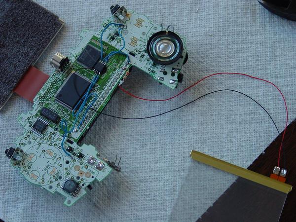
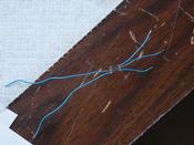
The resistor - note that the leads are trimmed down alot and bent to hit pin S2 exactly as well as avoid the flange sticking down from the GBA mainboard.

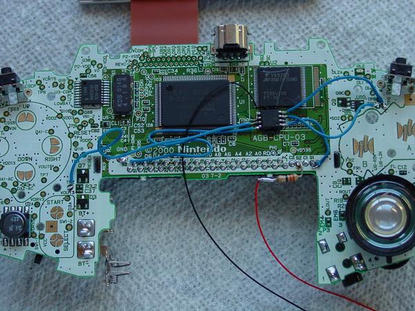
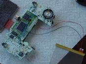
The dimmer chip with wires on all pins except 5 and 6, which go to the Afterburner light itself.

Note the dimmer chip "glued" to the mainboard via liquid electrical tape in a spot where none of the pins would touch any stray mainboard contacts. I applied the liquid electrical tape to the bottom of the dimmer chip using a cut-off Q-tip (no fuzzies) and then taped it down with electrical tape until the liquid electrical tape dried enough to hold the chip.

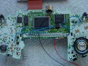
Closeup of the wiring additions to the mainboard. The black wire is simply stripped of insulation far enough to fold over both pins 5 and 6, where it's soldered to each pin.


Regarding lamination of the anti-reflective film to the LCD,

we followed the directions to the letter, from discovering which side of the anti-reflective film was sticky to giving the LCD quick dusting with the compressed air can to even applying it in one slow, smooth motion. (Actually, my fiancee did this latter part for me...) One thing we did different, however, was leave the "release liner" now on the top surface of the LCD installed until right before we put the LCD back into the window of the front case to limit exposure and risk of dust contamination.


As for the Afterburner lighting unit itself,

after placing it into the new front case, we also left the "release liner" on the easily accessible side until right before we put the LCD back in. This significantly reduced the amount of time the Afterburner was exposed to any falling dust/hair particles.


Putting it all back together

Reassembly was a little trickier than dissassembly. First, we had to remove the "release liner" from the accessible sides of the anti-reflective film (now attached to the LCD) and the Afterburner unit (now attached to the front case) and quickly (so as to reduce dust exposure) place the LCD into the front case.

Then, after getting all of the buttons and other plastic pieces in the correct spots and getting all the screws put it, I popped in batteries, a game, and fired it up to see the backlight working flawlessly (and with not a visible speck of dust or bubble in the display)! The only problem was that I had forgotten the light-conductive piece of plastic that appears as the power light on the case (the LED is actually mounted to the surface of the mainboard). So I disassembled my now-Afterburner-enhanced GBA, removed the light-conductive plastic part from my old front cover and placed it into its new home in the custom Afterburner front case, and reassembled.

See below for a photo of the LCD/front case assembly process (the image is clickable to download a larger version):


Getting ready to remove the "release liners" and drop the LCD into place.


All done!

For the last couple days, I've been really enjoying using my GBA in all sorts of lighting (although most frequently I use it in the evening with only a lamp on in another part of the room). No more panning to try to get light but not glare! Overall, I'm very satisfied with the end result, and would be more than willing to do this again, say, should my brother's GBA need one. I do notice a battery life difference, but I get plenty of warning from the GBA when the power light changes from green to red, and I can even dim the display a little bit to conserve power if I really can't... stop... gotta... make... it... to... that... save... point! Whew!


Go to my main console video game page.
Go to my home page.
Go to the polylith.com page.

Click here for Game Boy Advance items available on eBay.

One shop for all consoles - we ship fast!

Buy at GameStop.com!

Please consider visiting my sponsors (whom I also visit often and use myself), below...

Buy at GameStop.com

Top-Notch GameCube Accessories and Games
brendan@polylith.com